The API Seal Plans elaborated in this section are as defined by API 682 4th edition / API 610 10th edition.
These are standardized flushing piping arrangements that are widely used in the industry. Customer specific variants of these plans are possible.
API Piping plans help to ensure good conditions for mechanical seal operation as well as improving safety and pump reliability.
Please contact AESSEAL Systems Division for further details. Tel: +44 (0)28 9266 9966 Email: systems@aesseal.com For more information, and a video demonstrating the piping plan in operation, select a plan below
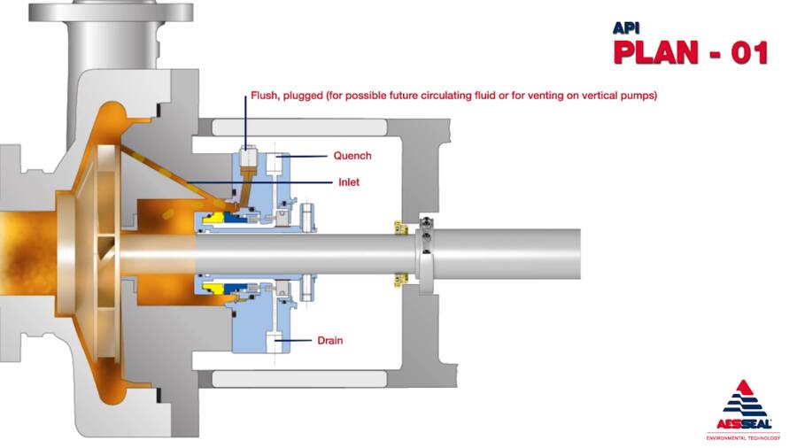
API Plan 01
Integrated (internal) product recirculation from pump discharge to seal chamber.
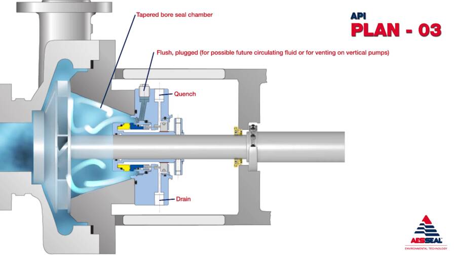
API Plan 03
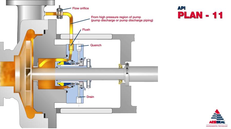
API Plan 11
Product recirculation from pump discharge to seal through a flow control orifice.
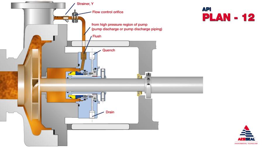
API Plan 12
Product recirculation from pump discharge through a Y strainer and a flow control orifice to seal chamber.
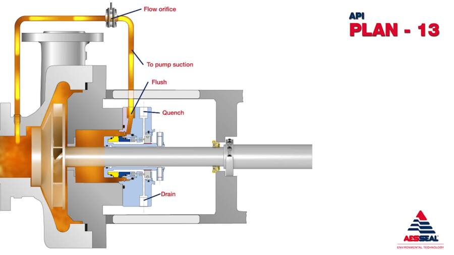
API Plan 13
Product recirculation from seal chamber to pump suction via a flow control orifice.
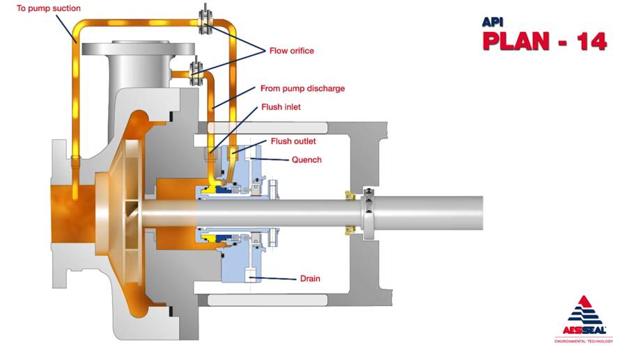
API Plan 14
Product recirculation from pump discharge to seal chamber through a flow control orifice and seal chamber back to suction through another flow control orifice.
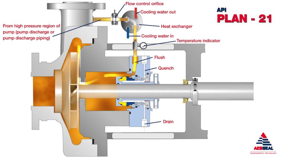
API Plan 21
Product recirculation from discharge through flow control orifice and heat exchanger to seal chamber.
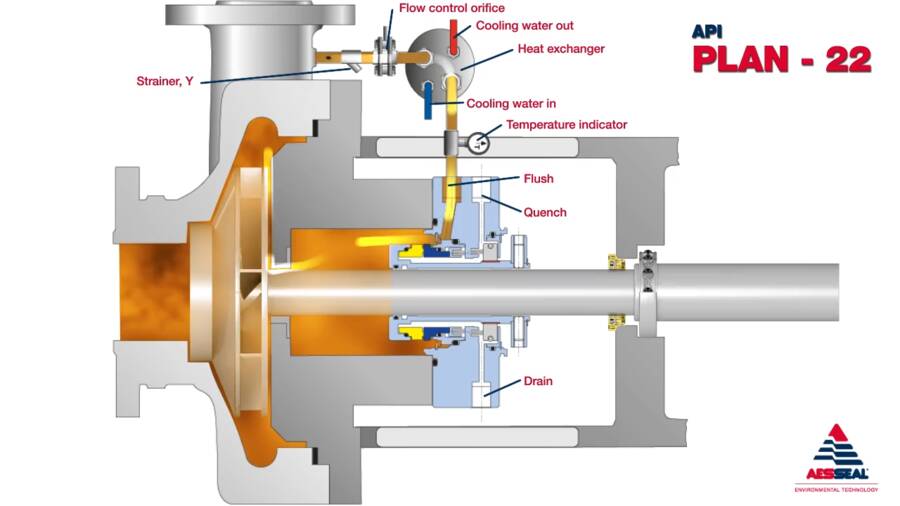
API Plan 22
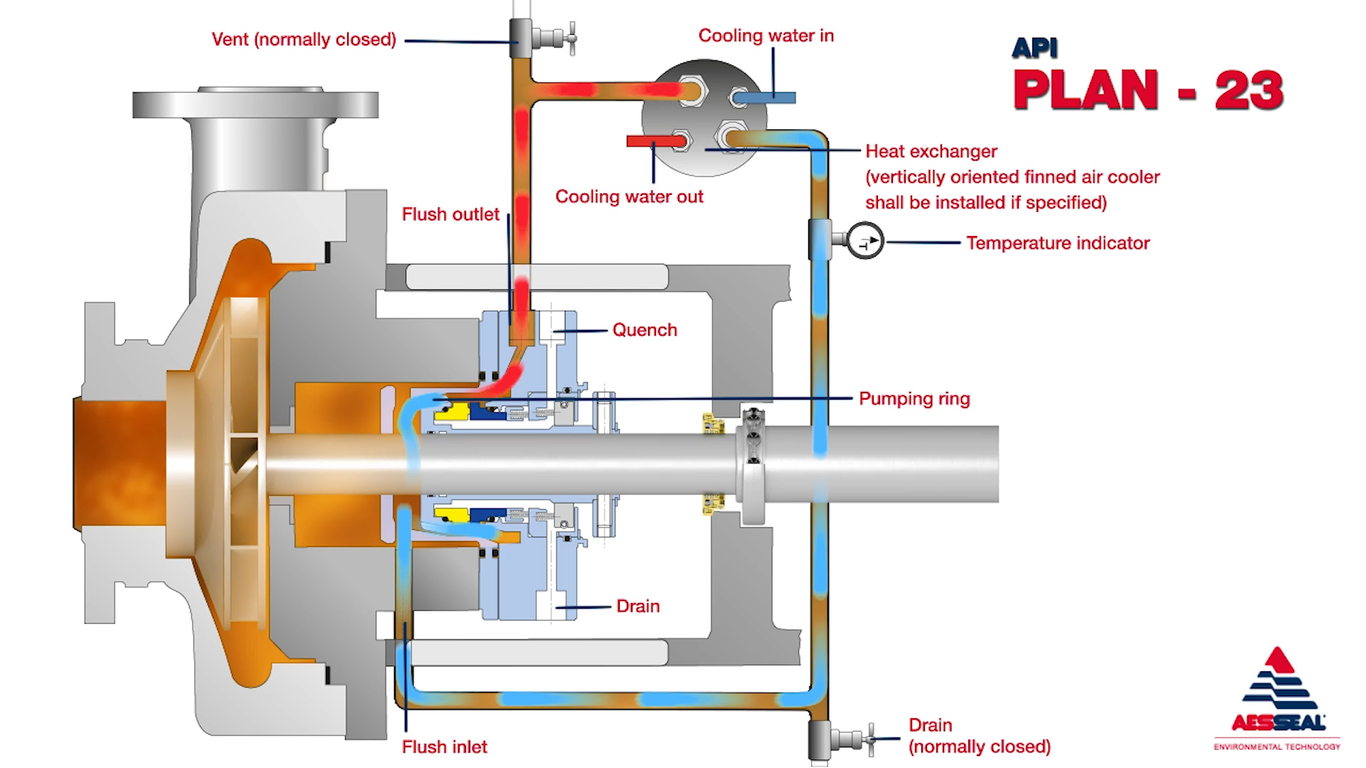
API Plan 23
Product recirculation from seal chamber to heat exchanger and back to seal chamber.
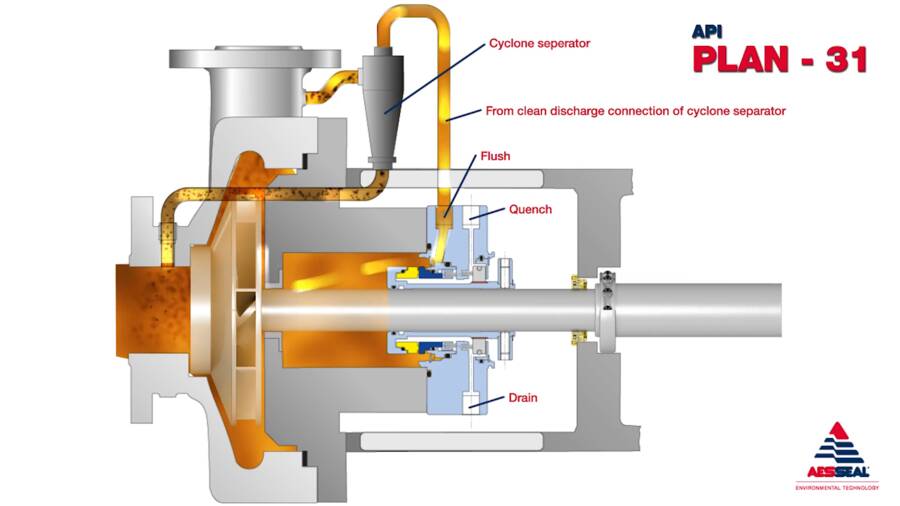
API Plan 31
Product recirculation from discharge through a cyclone separator, which directs clean fluid to the seal and solids back to pump suction.
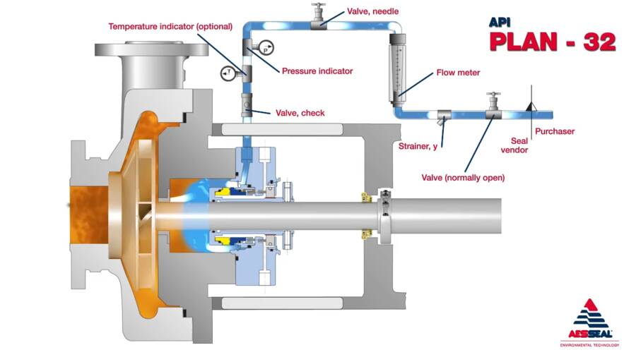
API Plan 32
Injection of clean or cool liquid from external source into the seal chamber.
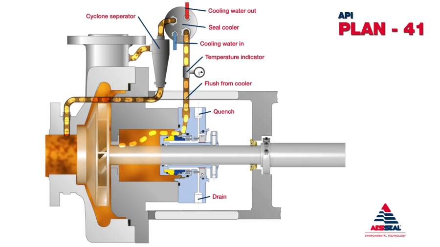
API Plan 41
Product recirculation from discharge through a cyclone separator and a heat exchanger to seal chamber.
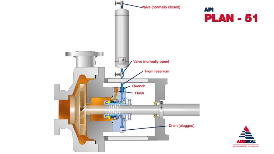
API Plan 51
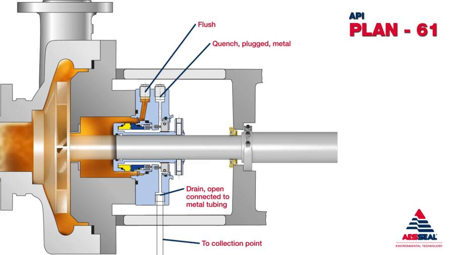
External reservoir providing a dead-ended blanket for fluid to the quench connection of the gland.
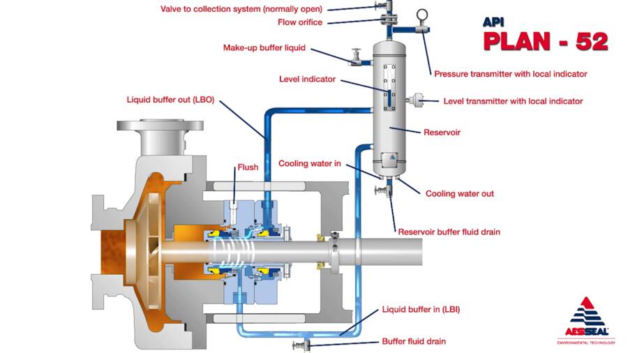
API Plan 52
Depressurised buffer fluid circulation in outboard seal of a dual seal configuration through a seal support system. Circulation is maintained by using pumping ring in running condition and by thermosyphon effect in stand still condition.
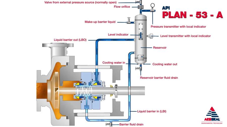
API Plan 53A
Pressurised barrier fluid circulation in outboard seal of dual seal configuration through a seal support system. Circulation is maintained by using pumping ring in running condition and with thermosyphon effect in stand still condition.
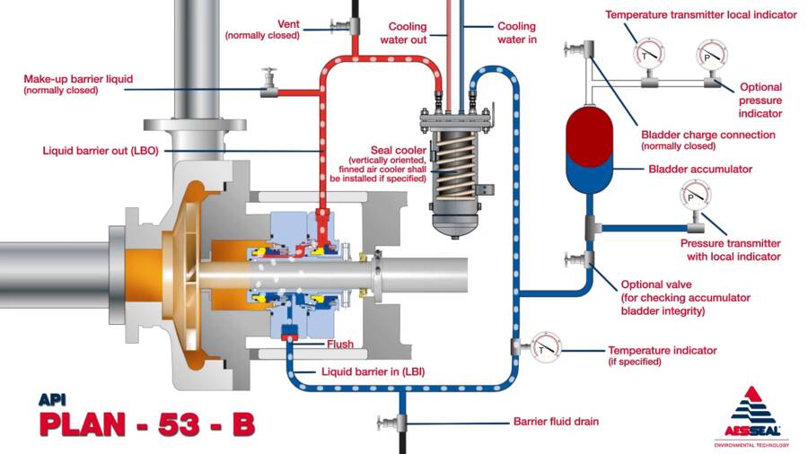
API Plan 53B
Plan 53B systems have been viewed as an engineering challenge around the world, often with long lead times. The innovative modular concept permits 12 modular options to be applied to create an API 53B System for any application.
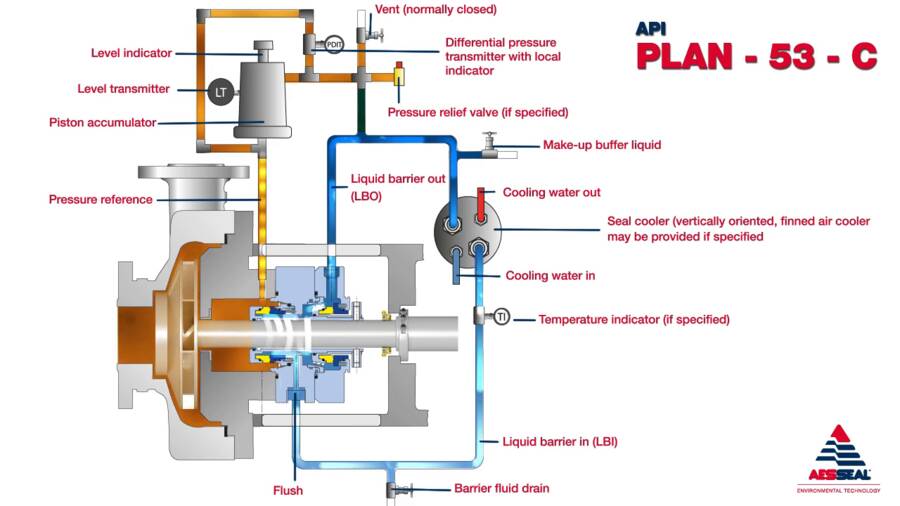
API Plan 53C
Pressurised barrier fluid circulation in outboard seal of dual seal configuration. Circulation is maintained by using pumping ring in running condition and with thermosyphon effect in stand still condition.
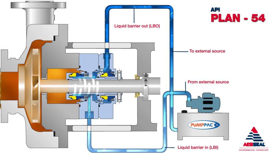
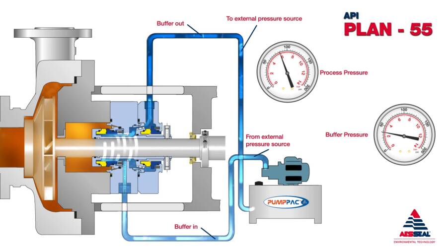
API Plan 54
Pressurised external barrier fluid circulation from a central pressure source or by a stand alone pumping unit (e.g. AESSEAL PUMPPAC™).
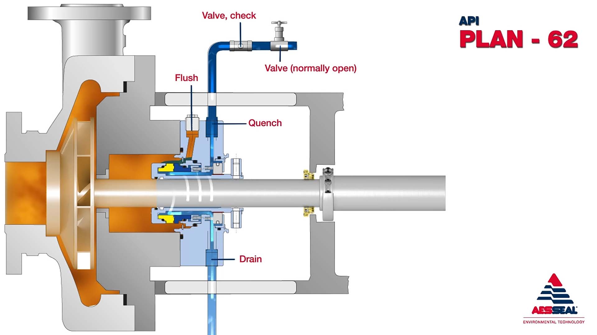
API Plan 62
An external fluid stream is brought to atmospheric side of the seal faces using quench and drain connections.
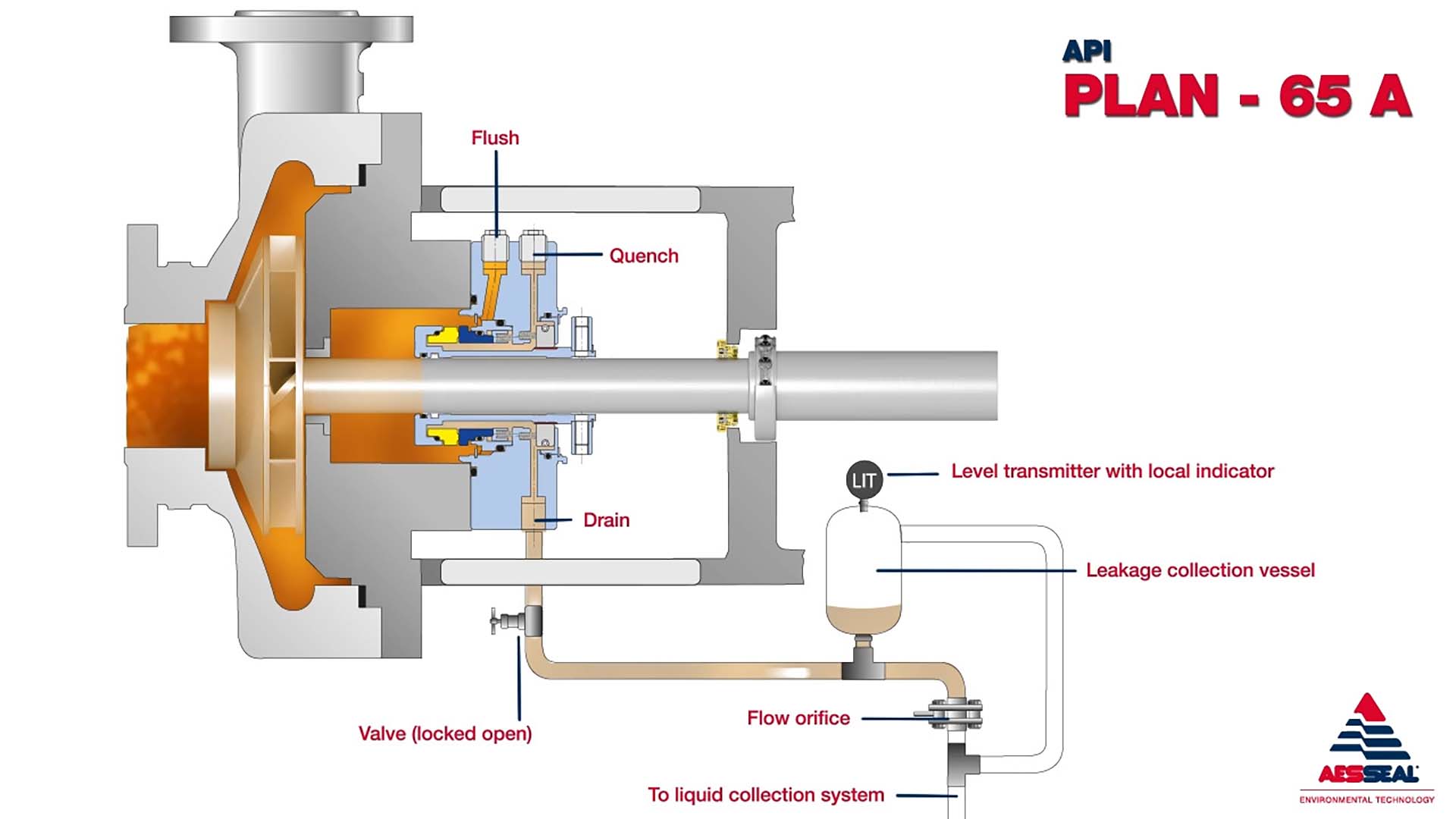
API Plan 65A
Leakage from seal faces is directed to a liquid collection system. A vessel with a high level alarm is provided for detection of excess leakage.
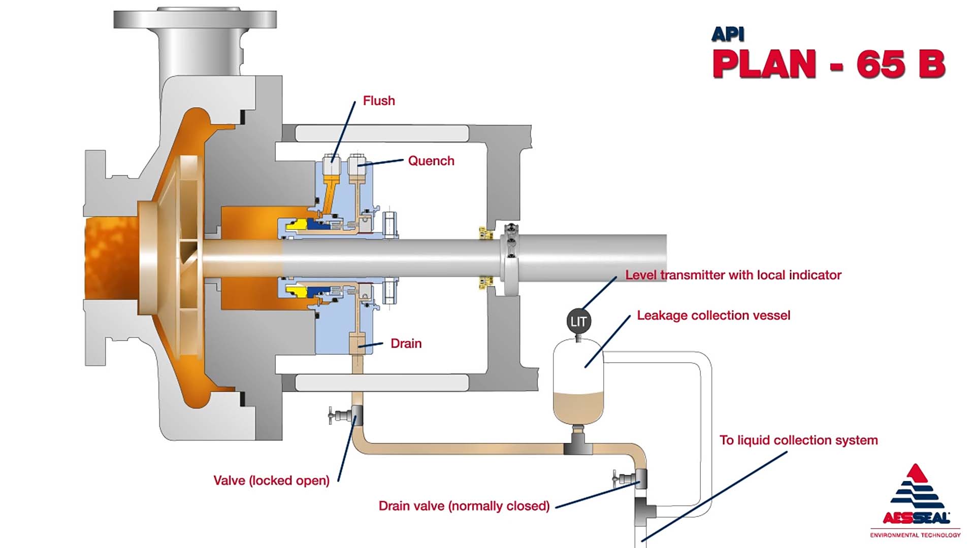
API Plan 65B
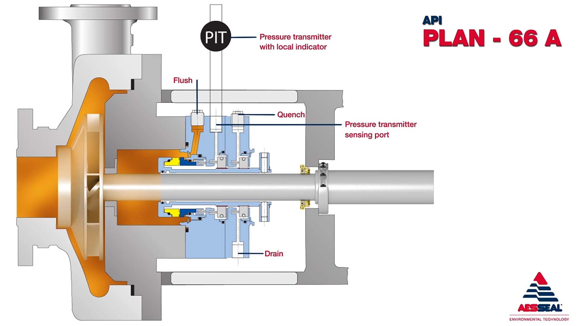
API Plan 66A
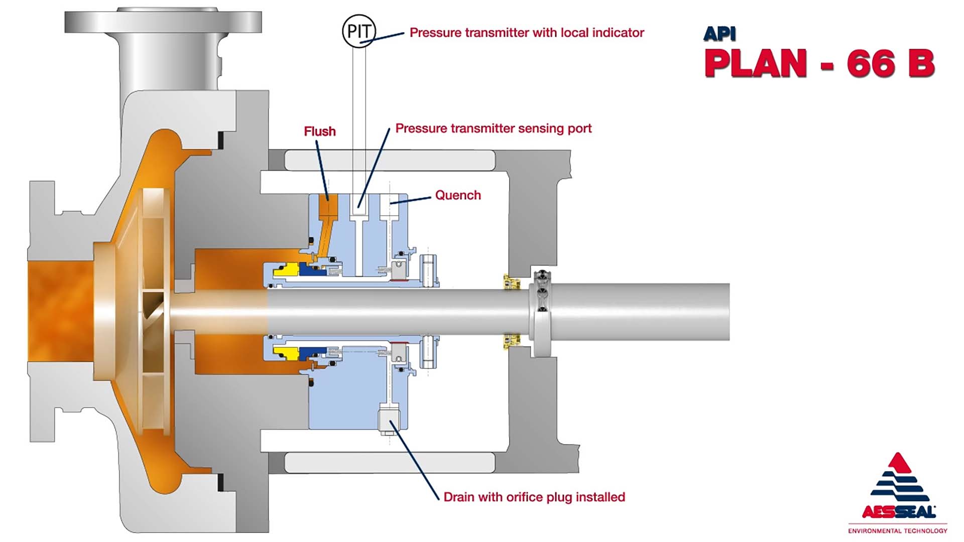
API Plan 66B
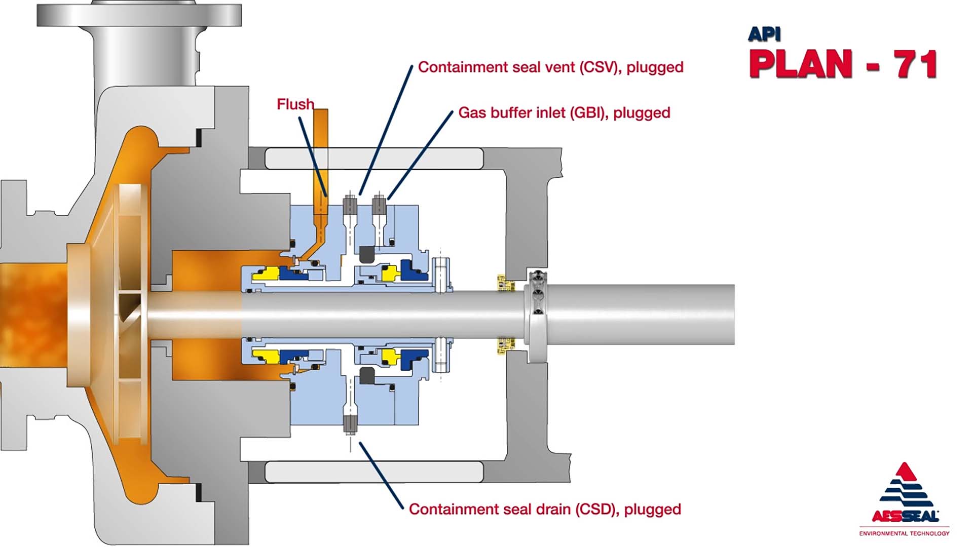
API Plan 71
Plugged connections for future provision to supply a buffer gas to a dual containment seal.
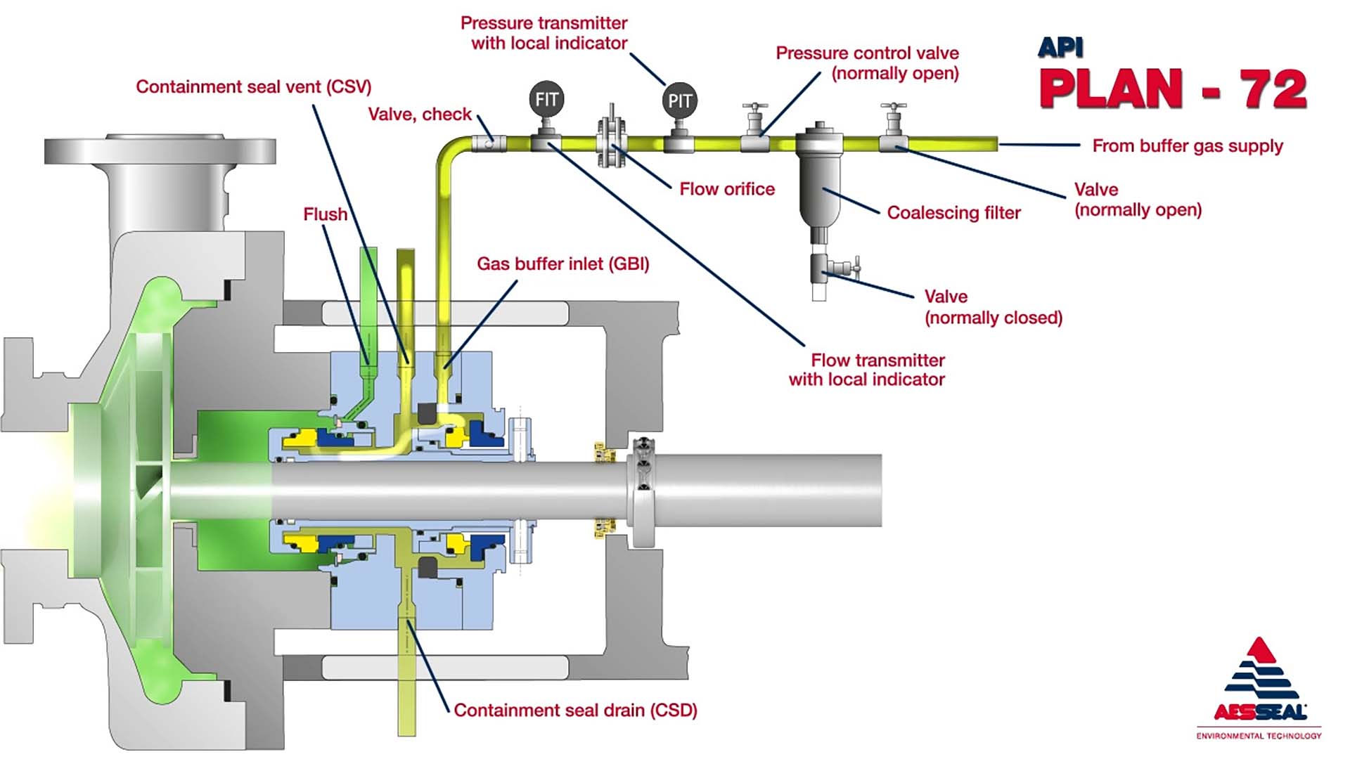
API Plan 72
Buffer gas is passed through the containment seal chamber to sweep inner seal leakage away from outer seal to a collection system and / or dilute the leakage.
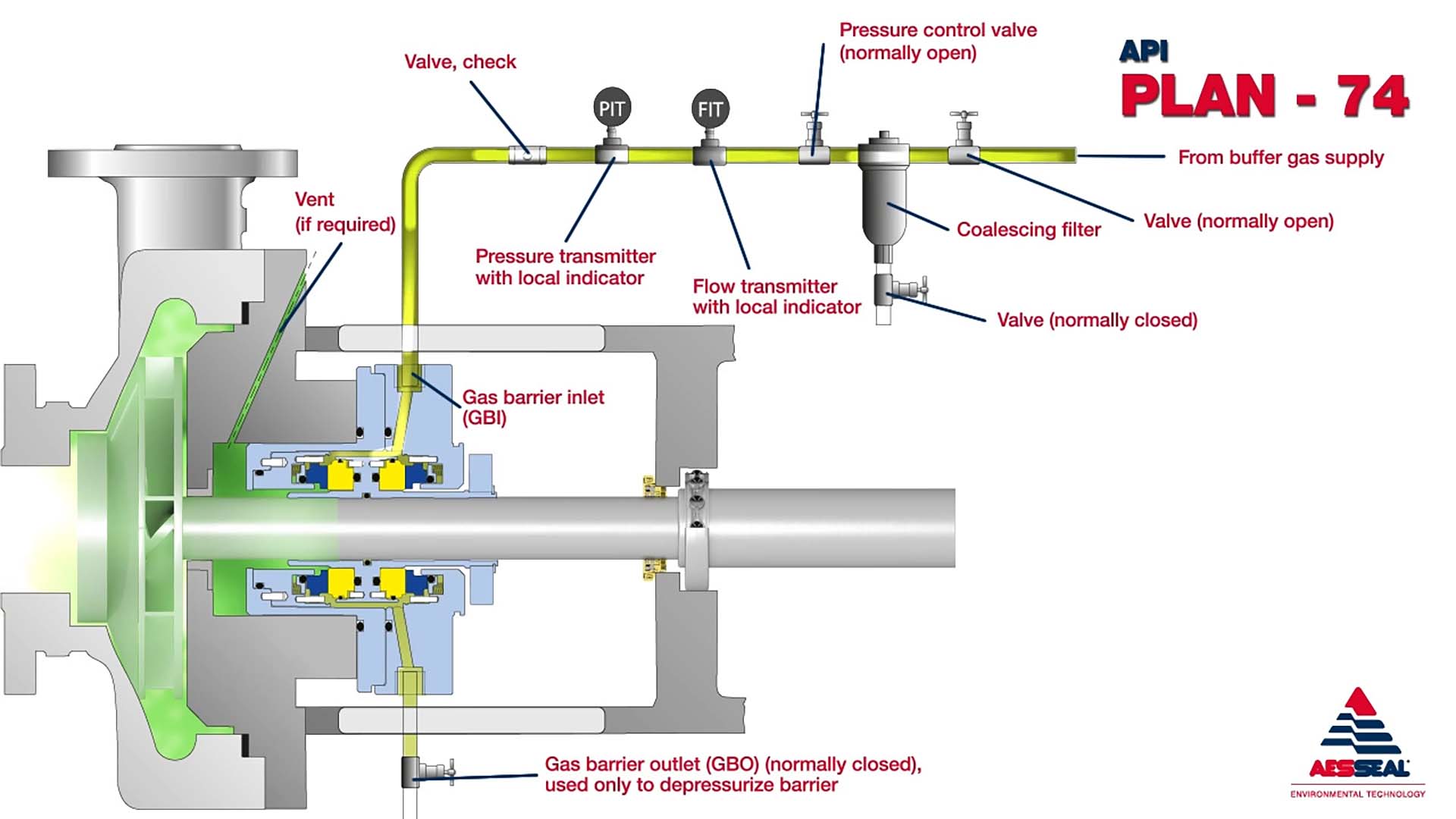
API Plan 74
Externally pressurised barrier gas supplied through a gas control system to a dual seal arrangement. An inert gas is used as a barrier gas.
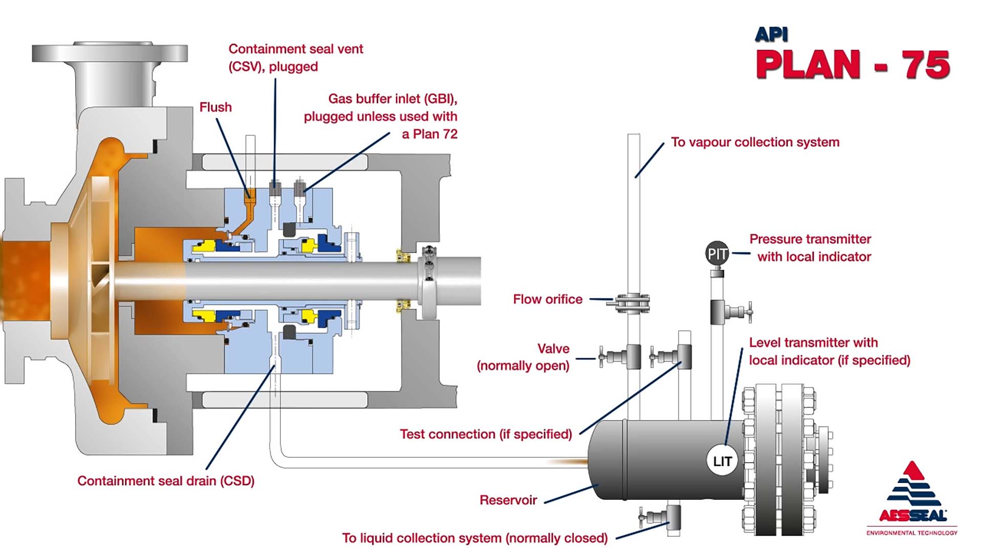
API Plan 75
Leakage of condensate from inboard seal of a dual containment seal is directed to a liquid collector.
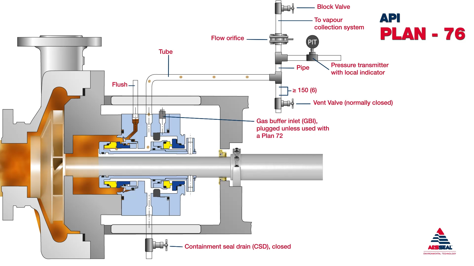
API Plan 76
Vapour leakages from inboard seal of dual containment seal are directed to a vapour recovery system via a vent connection.